Monday, April 1, 2013

Cryptech Proposal


Cryptech:
Reimagining the Household Safe

         For my midterm project, I will build a safe, but not just any ordinary safe. Why should a safe’s “user interface” be limited to a simple dial? For my project, I plan to reimagine the conventional lockbox, creating a new, dynamic and interactive way to open a safe. My safe – Cryptech – will use various sensors, variable resisters, knobs, buttons, (and anything else I can find) to make opening the safe a fun yet secure activity.

         The target audience for this project is anyone who is bored with the monotony of daily life. Rarely do we see examples of innovation in home appliances; toasters, mousetraps, toilets and safes have all remained virtually unchanged over the last few decades. Cryptech rebels against this stagnant lack of innovation, envisioning the safe as a fun-to-use product.

         Cryptech will work in the following way. First Cryptech will read the output from the various sensors. If these sensors all are turned to the correct level (as will be determined by the customizable code), then a green led will light up and a servomotor will rotate and unlock the latch for the safe. Then the safe will be accessible. If the sensors are not taking in the proper information, a red led will light up, signaling a failed attempt to access the safe. There will be a separate button for locking the safe once it is closed again.

List of Parts:
1.    Large wooden or metal box with hinge
2.    Some sort of locking mechanism that can be controlled by servomotor.
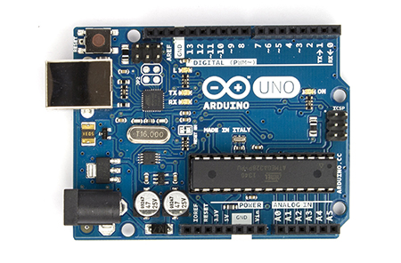
3.    Arduino microcontroller
4.    Breadboard and Wires and Resistors
5.    Servomotor
6.    Various sensors, including some of the following: Hall Effect Sensor, Capacitive Touch Sensor, Potentiometer, Photoresistor
7.    Various Switches and Buttons
8.    Various LEDs
9.    External power supply(?)
10.Other Sensors may be used…

Possible Issues: I think the hardest part for me will be creating the actual hardware: the safe itself. 
Monday, March 4, 2013

Baby Toy Assignment


For my project I built a toy designed to help put a baby to sleep. The concept is similar to the picture below, but on a very basic level. 


To build this toy, I attached two output devices to my Arduino. The first was a piezo speaker element, which I programmed to hum the tune of "Twinkle Twinkle Little Star". The second was a servo motor, which I programmed to sway back and forth to the rhythm of the song. I then attached a rope the servo motor and a tiny pillow to the end of the rope, causing the pillow to sway back and forth. Ideally, this soothing combination of auditory and visual stimuli would help put an infant to sleep.


My toy is limited in that it doesn't accept much user input, but this is hard when the target audience is an infant. In general, all toys of this nature are limited in that an infant easily "interact" with a toy. Usually, he/she is just a passive observer or interacts on a basic level by touching the object. Infants are good at "listening", but are challenged when it comes to "thinking" and "speaking". 

My project is also limited because of the speaker I have (I'm not sure how soothing the screeching noise of a piezo element would really be).

I didn't have a baby to test it on, so I decided to "simulate" the toy's use with the help of a few of my friends. In the demo is also a view of the circuit I used for this project. The demo can be seen below.

(Sorry for the bad sound quality! You have to listen very closely to hear the melody.)


Servo motor controlled by potentiometer with Arduino

1

Servo motor controlled by Pulse Width Modulation from an Arduino

Questions:

1. We add delay so we can see the incremental changes on the servo motor. Without delay, it would appear to move fluidly.

2. to get a 45 degree rotation, you must simply write toyServo.write(45);

3. It can... see my toy assignment for proof!

Transistor controlled by Arduino


Transistor as Amplifier


Questions:
1. Maximum resistance makes the sensor less sensitive. Minimum resistance makes the sensor more sensitive.

Transistor as Switch


Questions:

1. Because it is connected to a 10k Ohm resister instead of a 560 Ohm Resistor.
2. 1st Led = .005 I, 2nd Led = .0089I.